My Fiber7-X VyOS Config
Shortcuts
Updated Jun 2024: This Vyos 1.4 config is now broken if you use a recent vyos 1.5 rolling release. I made a new post here that mirrors this one, but with the correct syntax!#
Updated Aug 2022: After moving house I have been able to split my install between the basement and the house, so I bought myself an Dell Optiplex 7050 to be the VyOS router (the OTO is in the house), and then run a 10G fibre to the basement for the rest of the stuff. I think I will leave the post as is because the VM method is more interesting, but I will add a block on that below.
Updated Jul 2022: Following an exchange on Twatter it was clear to me that my explanation around the IPv6-PD usage was not very good, so I updated this section to clarify the prefix usage. I also feel that there is a gap here where the VyOS config should be able to pool the PD assignment, instead of me assigning it somewhere stupid like I did here.
As I discussed in my 10/25Gbit internet at home post, I recently moved away from a dedicated router appliance at home, to instead use a fancy(ish) NIC passed through directly to a VM. The point of this was to try and increase the throughput, whilst maintaining a low footprint in terms of power, complexity and cost. I guess we can argue about the complexity bit, but it wasn’t complex for me I guess. In this post I will break down the various sections of config to explain how they work and what they do.
To VM or not to VM#
In the homelab setting, its quite common to have hypervisors running for efficiency and WAF (wife acceptance factor). Initially, I was living in an apartment, and tbh I had a very limited amount of space for nerd stuff and this blog was intially authored during that time. When I moved to a house with a basement, I was able to distribute my nerdery more liberally. At this point, I deployed the hypervisor in the basement, and then started looking for something smaller to live next to the fibre installation in the living room.
One great option is the TinyMiniMicro setup made famous now by servethehome.com. I looked at a lot of these devices (waaay too much in fact), and found them to be really hard to source, and really expensive to acquire. That might work for your budget, so go check that out by all means. The Lenovo M92 tiny can expose an x8 riser if you look hard enough, and the HP t740 is also interesting.
The second obvious option is the Supermicro E series, combining Xeon chips with a BMC and lots of expansion options. I know people who have tried them, and are happy with them, but they cost between 500 and a grand, and more than anything else, theyre server class hardware, meaning hot, noisy, and ugly. Big no for the WAF…
I wanted to get as close to 100 bucks as I could, which left me with ex business SFF machines.
Picking an SFF machine was harder than I expected tbh. I wanted to ensure that it was small and quiet, but that it could handle 25G forwarding. Whilst I was investigating VPP for 100G rates in the DC, I established that I could forward 25G easy on a recent i5 CPU so I headed out to the auction sites to see what I could find.
The biggest issue I hit was actually the PCIe slots. I started looking at the HP z220, which is the baby SFF version of my existing tower server. It has a pair of PCIe x16 slots, an x4 slot and a traditional PCI for good measure. I also found one for 99CHF in St Gallen, so this was exciting. Turns out that one of these x16 slots is only x4 electrically, and the one that is x16, only supports GPUs. This became a trend. I had no idea that companies were deploying x16 slots without the wires inside? Why? I also find it odd that you cant put literally anything you like into the x16 slot. As it happens, this is correlated to CPU features - some Intel CPUs have a GPU on the CPU die, and some do not. As a result, there are BIOS configs that demand a GPU in the x16 slot. Weird, but logical.
Anyways, so began A LOT of reading hardware manuals, and checking support docs. I could probably list off all the ones that didnt work, but then this would be many pages long. Lets just say that the Dell Optiplex 7050 is a proven device. Inside I have an 7th Gen I5 (7500), an on board M.2 NVMe slot, one PCIe x16 and x4 (without restrictions on use), plus onboard graphics to ensure that the both PCIe slots are free for NICs.
I migrated my Mellanox CX4 2x25G card over and added an Intel i350 4x1G card, utilising the low profile brackets that came with these originally. If you dont have these brackets, google around and you will find them easy enough. I had to buy the i350 LP bracket and it cost me £6. At this point I booted VyOS from a USB stick installed it to the NVMe and then the remainder of the instructions apply as below.
The VM#
Assuming you arent interested in a baremetal install, then first, we have to deal with the VM itself. My hypervisor is VMware ESXi (free licence) running on an HP z620 tower workstation. There are ten-a-penny guides on how to setup ESXi and all that, plus I am sure someone is yelling PROXMOX at their screen right now. I have that running in a hyperconverged PVE/Ceph NUC cluster btw, I just don’t use it for this.
In ESXi I have a Mellanox ConnectX-4 dual port 25Gbit NIC for VyOS, and an Intel x710-DA2 10G card for the Hypervisor vSwitch uplinks. The Mellanox NIC is handed over fully to the VyOS VM. For that I had to also reserve the memory assignment for the VyOS VM as well. Given I have a lot of spare resource, I chose to assign 4x single core sockets and 8GB RAM. I am pretty certain I can cut this to just 1GB based on the historical consumption figures, but the CPU seems about right - during heavy downloading the CPU spikes up to at least one full core, and heavily multi threaded downloads at line rate can push it to the limit. I chose single core virtual sockets following a discussion with the Netgate performance engineers. They specifically advise people with bare metal installs to disable Hyper Threading and to fix recieve queues to specific cores as well. More on that later.
For VyOS, I chose to build my own “production image” using the docker based build tool. There are a few different opinions on this, but since they started offering the Enterprise Edition, obtaining the free version became a little janky. The website offers the so called “rolling” release, which is built on every day when a newer commits to master are made. This means it is bleeding edge feature wise, and should be test complete, but not necessarily stable. Rather than try a bunch and work out what my stable would be, I chose to follow the community recommendation and build an image from the “current” 1.4 branch. The was all the instructions I needed. I have since done a bunch of upgrades by building newer images and uploading them via scp, and simply activating them - it’s very easy to maintain.
So having configured the Mellanox NIC for passthrough and rebooted my ESXi box, then configuring the VM and adding a basic VMXNET3 for MGMT plus the PCI device for the WAN and inside trunk interface, I booted my ISO and ran the basic install process.
The Initial Config#
Trying to type in loads of things to the VMware Remote Console without copy/paste and all that stuff is sort of annoying, so I always go with a basic config that allows me to SSH in and complete the config in a terminal. Firstly, I double checked the MAC addresses on the interfaces so that I knew which one was which. Thankfully the MGMT interface came up as eth0, and the CX4 ports were eth1 and eth2. Easy peasy.
Here are the basic commands I ran to sort out remote access:
set interfaces ethernet eth0 address '10.31.74.1/27'
set interfaces ethernet eth0 description 'MGMT'
set system domain-name 'mydomain.co.uk'
set system host-name 'vyos01'
set service ssh listen-address 10.31.74.1
set service ssh port 22
Commit and Save and then swap to a terminal attached to the MGMT LAN
The Network Design#
My home network is quite simple really (for a network specialist). There is a MGMT interface (eth0), a WAN interface (eth1) and an inside interface (eth2). WAN is a routed port and MGMT is an untagged member of vlan10. eth2 is a dot1q trunk and carries two VLANs. All VLANs are represented on the switch, and most host ports are untagged members of VLAN9 for Home use. VLAN8 is there for the Lab to be able to use the 10G directly. This isn’t possible outside of the Hypervisor yet, but i’m looking into alternatives to that CSS610 with at least 4 SFP+ ports to help with this.
Note: I like to use asciiflow for markdown friendly diagrams. Blogger seems to have a fixed width here, and this broke the ASCIIArt, so here you have a screenshot.
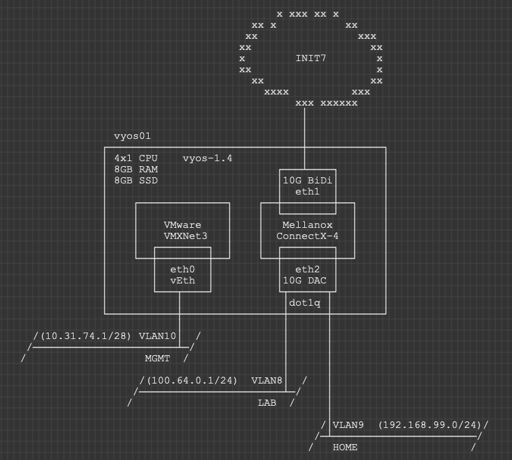
Physically, there is quite the sprawl of stuff. I laid out all the assets that use a cabled connection only. The Wifi attached stuff (notably the tons of IoT things for HomeAssistant) would just clutter it all up even further.
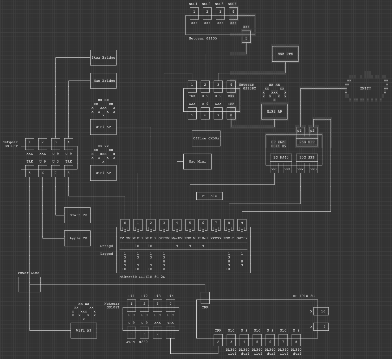
When you see it on a picture, it’s kinda obvious that whilst logically simple, my network is far from simple in practical terms. A lot of it is accumulated crap I should probably destroy, but for now, this is what I am working with.
The Core Config#
Here we look at the minimum viable product configs. This is what you need to make VyOS work as a firewall/router in the home setting.
WAN Interface#
set interfaces ethernet eth1 address 'dhcp'
set interfaces ethernet eth1 description 'Init7'
set protocols static route 0.0.0.0/0 dhcp-interface 'eth1'
set system name-server 'eth1'
That is all you need to have the router itself talk to the internet. Now we need to setup the client side.
LAN Interface#
My config has the inside configured as a trunk port and then a subinterface (vif) is configured for the VLAN:
set interfaces ethernet eth2 vif 9 address '192.168.99.1/24'
Comically that is pretty much all you need to make the most simple router of all time. We don’t want that tho. We want something a bit more useful than this!
Router Services#
In my network, I delegate the internal DHCP Server role to a PiHole that runs on a Pi3 in the closet. I do use DHCP in the Management Zone tho, and that lives here on the VyOS box.
set service dhcp-server listen-address '10.31.74.1'
set service dhcp-server shared-network-name mgmt authoritative
set service dhcp-server shared-network-name mgmt description 'MGMT'
set service dhcp-server shared-network-name mgmt name-server '192.168.99.4'
set service dhcp-server shared-network-name mgmt name-server '192.168.99.2'
set service dhcp-server shared-network-name mgmt ping-check
set service dhcp-server shared-network-name mgmt subnet 10.31.74.0/27 default-router '10.31.74.1'
set service dhcp-server shared-network-name mgmt subnet 10.31.74.0/27 range scope1 start '10.31.74.2'
set service dhcp-server shared-network-name mgmt subnet 10.31.74.0/27 range scope1 stop '10.31.74.30'
Lets assume you want some specific IPs on things in that management zone so you can have polling in the future. Here is the couple of lines you need for a reservation in that segment
set service dhcp-server shared-network-name mgmt subnet 10.31.74.0/27 static-mapping core-sw ip-address '10.31.74.2'
set service dhcp-server shared-network-name mgmt subnet 10.31.74.0/27 static-mapping core-sw mac-address '2c:c8:1b:6a:c8:8d'
Logging is important, so lets ensure its all enabled
set system syslog global facility all level 'info'
set system syslog global facility protocols level 'debug'
Next up, to ensure our logs are helpful, we setup NTP to ensure the clock is synced at all times
set system ntp server 0.ch.pool.ntp.org pool
set system ntp server 1.ch.pool.ntp.org pool
And to ensure that LLDP works both ways, we set this up on our internal interfaces:
set service lldp interface eth0
set service lldp interface eth2.9
set service lldp management-address '10.31.74.1'
I, for reasons of lazyness would also like SSH to work over the Home interface
set service ssh listen-address '192.168.99.1'
Finally, we want the OS to be tuned for performance, cos we are going to use a fast feed (may require reboot). A description of what this does is in the docs.
set system option performance 'throughput'
NAT Setup#
There is not a lot of point having an IPv4 firewall/router if it doesnt do NAT. Here we do all the fun things and stuff to make IPv4 source NAT work. Here I use 77 as a rule ID ‘prefix’ and then have dedicated rules for each source subnet. There are other ways to do this, but this is more surgical and verbose is my preference when it comes to things like NAT and Firewalls.
set nat source rule 771 outbound-interface 'eth1'
set nat source rule 771 source address '192.168.99.0/24'
set nat source rule 771 translation address 'masquerade'
set nat source rule 772 outbound-interface 'eth1'
set nat source rule 772 source address '10.31.74.0/24'
set nat source rule 772 translation address 'masquerade'
Now assuming we want to allow some inbound services from the internet, we need some destination NAT as well… I picked the rule number for a reason, but I guess its obvious this idea doesnt scale well. I kinda don’t care that much tho ;)
set nat destination rule 443 description 'HTTPS to Ingress'
set nat destination rule 443 destination port '443'
set nat destination rule 443 inbound-interface 'eth1'
set nat destination rule 443 protocol 'tcp_udp'
set nat destination rule 443 translation address '192.168.99.252'
set nat destination rule 443 translation port '443'
Zone Based Firewall#
This is going to be a bit more chunky. ZBF is universally agreed to be more scalable, but it is also universally agreed to suck balls to configure. The first build is annoyingly slow, but once it is in, adding interfaces into zones is trivial and policy can be inherited/deduplicated, which I think is a big win. I spent a little bit of time on automating this in Nornir, which I will publish soon. I think I could probably write an entire essay on ZBF concepts, so I will save you my ramblings and refer you to the Docs instead: VyOS Zone-Based Firewall Guide
ZBF - Basics#
A lot of this is probably default config, but since VyOS configdb is idempotent, if you paste a command that already exists, it will just skip on past.
set firewall all-ping 'enable'
set firewall broadcast-ping 'disable'
set firewall config-trap 'disable'
set firewall ip-src-route 'disable'
set firewall log-martians 'enable'
set firewall receive-redirects 'disable'
set firewall receive-redirects 'disable'
set firewall send-redirects 'enable'
set firewall source-validation 'disable'
set firewall syn-cookies 'enable'
set firewall twa-hazards-protection 'disable'
set system conntrack modules ftp
set system conntrack modules h323
set system conntrack modules nfs
set system conntrack modules pptp
set system conntrack modules sip
set system conntrack modules sqlnet
set system conntrack modules tftp
I also defined a group for inside networks that can be used later on. Feel free to define as many network and service groups as you like to clean up your config.
set firewall group network-group inside-nets network '192.168.99.0/24'
set firewall group network-group inside-nets network '10.31.74.0/27'
ZBF - Policies#
So we need policies before we can apply those to zones. The Zone assignments refer to the policy names, so lets make them first.
In each policy I use a default-action drop, which is a sort of best practice. In more trusted settings, you might want a default permit (outbound from LAN to WAN for example), and typically people will use a default-action of accept. I prefer to put a drop policy in and then a single rule to permit all at rule 1, since if something horrible happens and I need to block something outbound (malware C2 or somesuch), I can insert a rule above to drop something specific. I can also change that rule 1 to only permit certain ports or protocols and drop all others. Basically, better set a sane default and override it, than have to change the whole policy in an emergency, which might have undesired consequences, thus compounding an already shitty situation.
I like to put a description in but lets face it, its pretty self describing.
I also enable the default log statement so all firewall rule hits are logged. This is again a good best practice. You wont care until you need this and then future you will thank you for this.
ZBF - Policies - Local#
Local policies are those that originate or terminate on the VyOS instance directly. We need traffic in both directions (inbound and outbound) from and to the router, so we have four policies here.
set firewall name lan-local default-action 'drop'
set firewall name lan-local description 'LAN to This Router IPv4'
set firewall name lan-local enable-default-log
set firewall name lan-local rule 1 action 'accept'
set firewall name lan-local rule 1 description 'Better this than default allow and change later!'

set firewall name local-lan default-action 'drop'
set firewall name local-lan description 'This Firewall to LAN IPv4'
set firewall name local-lan enable-default-log
set firewall name local-lan rule 1 action 'accept'
set firewall name local-lan rule 1 description 'Better this than default allow and want to change later!'

set firewall name wan-local default-action 'drop'
set firewall name wan-local description 'WAN to This Device IPv4'
set firewall name wan-local enable-default-log
set firewall name wan-local rule 1 action 'accept'
set firewall name wan-local rule 1 state established 'enable'
set firewall name wan-local rule 1 state related 'enable'
set firewall name wan-local rule 2 action 'drop'
set firewall name wan-local rule 2 state invalid 'enable'
set firewall name wan-local rule 3 action 'accept'
set firewall name wan-local rule 3 description 'DHCP Replies'
set firewall name wan-local rule 3 destination port '67,68'
set firewall name wan-local rule 3 protocol 'udp'
set firewall name wan-local rule 3 source port '67,68'

set firewall name local-wan default-action 'drop'
set firewall name local-wan description 'This Router to WAN IPv4'
set firewall name local-wan enable-default-log
set firewall name local-wan rule 1 action 'accept'
Inbound policies (lan-local and wan-local) are all about things talking to the router directly. LAN side I allow anything and WAN side we block everything not related to an existing “inflight” outbound conn, but I also had to enable the inbound DHCP flows since these are stateless.
Outbound I again just permit all the things.
ZBF - Policies - Transit#
Transit policies are ones where the flow is designed to transit through the router. In iptables world these are FORWARD rules.
set firewall name lan-wan default-action 'drop'
set firewall name lan-wan description 'LAN to WAN IPv4'
set firewall name lan-wan enable-default-log
set firewall name lan-wan rule 1 action 'accept'
set firewall name lan-wan rule 1 description 'better this than default accept and then you change your mind!'

set firewall name wan-lan default-action 'drop'
set firewall name wan-lan description 'WAN to LAN IPv4'
set firewall name wan-lan enable-default-log
set firewall name wan-lan rule 1 action 'accept'
set firewall name wan-lan rule 1 state established 'enable'
set firewall name wan-lan rule 1 state related 'enable'
set firewall name wan-lan rule 2 action 'drop'
set firewall name wan-lan rule 2 state invalid 'enable'
set firewall name wan-lan rule 443 action 'accept'
set firewall name wan-lan rule 443 description 'HTTPS to ingress'
set firewall name wan-lan rule 443 destination address '192.168.99.252'
set firewall name wan-lan rule 443 destination port '443'
set firewall name wan-lan rule 443 protocol 'tcp_udp'
As well as the default log and description, I have a rule that matches our destination NAT rule we defined previously. Notice how we use the “real” IP of the host on the inside. This can catch some people out who are used to firewall rules referring to the mapped IP on the outside of the firewall. I chose the same rule ID as the NAT rule ID, but that is my personal choice, there is no requirement to syncronise these rule IDs.
ZBF - Zones#
Now that we have policies, we can assign these policies to zones. Zones and interfaces are a one-to-many mapping, i.e. one Zone can contain many interfaces, but for the avoidance of doubt, an interface can only exist in one Zone ;)
set zone-policy zone wan default-action 'drop'
set zone-policy zone wan from lan firewall name 'lan-wan'
set zone-policy zone wan from local firewall name 'local-wan'
set zone-policy zone wan interface 'eth1'

set zone-policy zone lan default-action 'drop'
set zone-policy zone lan from local firewall name 'local-lan'
set zone-policy zone lan from wan firewall name 'wan-lan'
set zone-policy zone lan interface 'eth2.9'
set zone-policy zone lan interface 'eth0'

set zone-policy zone local default-action 'drop'
set zone-policy zone local from lan firewall name 'lan-local'
set zone-policy zone local from wan firewall name 'wan-local'
set zone-policy zone local local-zone
Here we created our three zones called wan, lan and local. We then assigned the firewall policies “inbound”, and finally assigned interfaces to the zones. Note the special “local-zone” flag for that local zone.
A lot of people then go on to ask, what happens to traffic between interfaces within one zone, in our example. eth0 and eth2.9. These flows are unrestricted - think of them as a plain routed interface.
Note: MGMT and User traffic? Routed? No FW? WHATTTT? - This is my house, I don’t care. Don’t @ me.
At this point you should have a fully operational internet connection on eth0 and eth2.9, providing you legacy internet access. Whats legacy internet access? IPv4 only of course!
Enabling IPv6#
First, I should point out that my approach here is rather opinionated. Some will argue it is literally stupid. I also do not care about this ;)
The point of IPv6 was to deliver enough internet addressing that we could never run out like we have with IPv4. A side benefit of this was that NAT was essentially deprecated, since we dont need to share one public IP with many clients inside a LAN zone. For many, the obvious benefit is that all devices in your LAN get a public routable IPv6 address, and you control the flows on the border with a firewall, just like normal. In my workplace we have dual internet feeds, and we get IPv6 addressing from both. Which IP address pool should we use to assign IPv6 addresses to clients? If both, which should a client machine use to route outbound?
In some settings, the SLAAC addressing system makes a lot of sense, but in an enterprise, I still need concrete services, which means predictable, reliable DNS/IPs. Ultimately, I will find myself using some form of static addressing. Now, what happens when I change ISP? That /48 I got from the first one is now not mine, and I have to re-address my entire LAN. This is unsustainable.
Thankfully, someone thought of all of these use cases and came up with Unique Local Addressing, and Prefix Translation (sometimes known as NAT66) as a solution. With ULA, I can generate (and optionally register) a ULA prefix that should be globally unique for my site, and use that for all internal addressing purposes. I then configure NAT66 to swap the first 48 or 64 bits of my 128 bit IPv6 address to one from our IPv6 Prefix delegation we recieved from upstream. If the ISP assigns us something new, or we change ISP (via failover or physically replacing a supplier), the prefix substitution just does the work for me. So inside my LAN, I have a private address, from a single site specific prefix, and then as traffic heads outside my LAN I have an otherwise identical address, but with an internet routable prefix.
e.g. Inside my LAN my PC looks like this:
% ifconfig
   en0: flags=8863<UP,BROADCAST,SMART,RUNNING,SIMPLEX,MULTICAST> mtu 1500
        options=50b<RXCSUM,TXCSUM,VLAN_HWTAGGING,AV,CHANNEL_IO>
        ether 00:3e:e1:c9:28:10
        inet6 fe80::ca2:34c4:8b00:daa8%en0 prefixlen 64 secured scopeid 0x4
        inet6 fda4:7911:df45:9:4cc:2a5a:8ee5:a917 prefixlen 64 autoconf secured
        inet 192.168.99.111 netmask 0xffffff00 broadcast 192.168.99.255
        nd6 options=201<PERFORMNUD,DAD>
        media: autoselect (1000baseT <full-duplex>)
        status: active
but on the internet, i am seen as:
% curl -6 https://ifconfig.co
2a02:168:4047:9:4cc:2a5a:8ee5:a917
All that happened is we swapped that first 48 bits.
Now some gamers might be screaming at me right now, I have no idea if this is good or bad for you guys, but given it is a 1:1 mapping, it is probably ok tbh. We will see in the comments I guess.
IPv6 - Interfaces#
Init7 offer a /48 and in my case, whilst it is assigned via DHCPv6, this assignment is reserved for me in their system. It’s logically static. Your mileage may vary, and I know of at least two other init7 customers who had their /48 change, but randomly. This in essence is why I follow this NAT process btw. So first we need to enable dhcpv6 on our internet interface and request an IPv6 prefix delegation that we will anchor to an inside interface for operational reasons. If there were a better way to do this, i would, since we dont actually use this IP on this interface in daily use, but we need to anchor it somewhere. If you are concerned, you could bind this to a non existent VLAN maybe.
set interfaces ethernet eth1 ipv6 address autoconf
set interfaces ethernet eth1 address 'dhcpv6'
set interfaces ethernet eth1 dhcpv6-options pd 0 interface eth2.9 address '9'
set interfaces ethernet eth1 dhcpv6-options pd 0 length '48'
So our WAN interface uses SLAAC for the interface IP, getting an address in a /64 owned and operated by Init7. We then use DHCPv6 to request an IPv6 /48 that we can assign to the inside interfaces of our router.
Here I am cheating and statically assigning the :9::1/64 from our site /48 to the vlan 9 under the eth2 interface. I follow this scheme for all VLANs since I am unimaginative.
I assume you have gone and got your own ULA prefix and registered it. Dont use mine!
set interfaces ethernet eth2 vif 9 address 'fda4:7911:df45:9::1/64'
When you commit this, you can query your eth2.9 interface to see the PD you got. Here you see I got 2a02:168:4047::9/64. I am hopeful there is a better way to do this. Right now I cant see it tho.
jhow@rtr-iojh-vyos01:~$ show interfaces ethernet eth2.9
eth2.9@eth2: <BROADCAST,MULTICAST,UP,LOWER_UP> mtu 1500 qdisc noqueue state UP group default qlen 1000
    link/ether 50:6b:4b:1c:09:fb brd ff:ff:ff:ff:ff:ff
    inet 192.168.99.1/24 brd 192.168.99.255 scope global eth2.9
       valid_lft forever preferred_lft forever
    inet6 2a02:168:4047::9/64 scope global
       valid_lft forever preferred_lft forever
    inet6 fda4:7911:df45:9::1/64 scope global
       valid_lft forever preferred_lft forever
    inet6 fe80::526b:4bff:fe1c:9fb/64 scope link
       valid_lft forever preferred_lft forever
IPv6 - NAT66#
Here we do the magic prefix switcheroo. I have a rule for each vlan ID so I can swap the /64 in a granular way. Realistically, I could compress this to a /48 on a single rule, but again, I like to be verbose so people know exactly what is happening at each stage.
set nat66 destination rule 9 destination address '2a02:168:4047:9::/64'
set nat66 destination rule 9 inbound-interface 'eth1'
set nat66 destination rule 9 translation address 'fda4:7911:df45:9::/64'
set nat66 source rule 9 outbound-interface 'eth1'
set nat66 source rule 9 source prefix 'fda4:7911:df45:9::/64'
set nat66 source rule 9 translation address '2a02:168:4047:9::/64'
IPv6 - Router Advertisements#
Setup Router Advertisements on your inside interface, ensuring internal clients get a random SLAAC address from my ULA pool, and DNS Servers.
set service router-advert interface eth2.9 name-server '2606:4700:4700::1111'
set service router-advert interface eth2.9 name-server '2606:4700:4700::1001'
set service router-advert interface eth2.9 prefix fda4:7911:df45:9::/64
IPv6 - Firewalling#
Here it is essentially a copy paste of the v4 rules from earlier but edited to a v6 approach.
set firewall ipv6-receive-redirects 'disable'
set firewall ipv6-src-route 'disable'

set firewall ipv6-name lan-local-6 default-action 'drop'
set firewall ipv6-name lan-local-6 description 'LAN to This Router IPv6'
set firewall ipv6-name lan-local-6 enable-default-log
set firewall ipv6-name lan-local-6 rule 1 action 'accept'

set firewall ipv6-name local-lan-6 default-action 'drop'
set firewall ipv6-name local-lan-6 description 'This router to LAN IPv6'
set firewall ipv6-name local-lan-6 enable-default-log
set firewall ipv6-name local-lan-6 rule 1 action 'accept'
set firewall ipv6-name local-lan-6 rule 1 description 'better this than default allow and want to change later!'

set firewall ipv6-name local-wan-6 default-action 'drop'
set firewall ipv6-name local-wan-6 description 'This Router to WAN IPv6'
set firewall ipv6-name local-wan-6 enable-default-log
set firewall ipv6-name local-wan-6 rule 1 action 'accept'

set firewall ipv6-name wan-local-6 default-action 'drop'
set firewall ipv6-name wan-local-6 description 'WAN to This Device IPv6'
set firewall ipv6-name wan-local-6 rule 1 action 'accept'
set firewall ipv6-name wan-local-6 rule 1 state established 'enable'
set firewall ipv6-name wan-local-6 rule 1 state related 'enable'
set firewall ipv6-name wan-local-6 rule 2 action 'accept'
set firewall ipv6-name wan-local-6 rule 2 protocol 'icmpv6'
set firewall ipv6-name wan-local-6 rule 3 action 'accept'
set firewall ipv6-name wan-local-6 rule 3 description 'DHCPv6 Replies'
set firewall ipv6-name wan-local-6 rule 3 destination port '546'
set firewall ipv6-name wan-local-6 rule 3 protocol 'udp'
set firewall ipv6-name wan-local-6 rule 3 source port '547'

set firewall ipv6-name wan-lan-6 default-action 'drop'
set firewall ipv6-name wan-lan-6 description 'WAN to LAN IPv6'
set firewall ipv6-name wan-lan-6 enable-default-log
set firewall ipv6-name wan-lan-6 rule 1 action 'accept'
set firewall ipv6-name wan-lan-6 rule 1 state established 'enable'
set firewall ipv6-name wan-lan-6 rule 1 state related 'enable'
set firewall ipv6-name wan-lan-6 rule 2 action 'accept'
set firewall ipv6-name wan-lan-6 rule 2 protocol 'icmpv6'

set firewall ipv6-name lan-wan-6 default-action 'drop'
set firewall ipv6-name lan-wan-6 description 'LAN to WAN IPv6'
set firewall ipv6-name lan-wan-6 enable-default-log
set firewall ipv6-name lan-wan-6 rule 1 action 'accept'
set firewall ipv6-name lan-wan-6 rule 1 description 'better this than default accept and then you change your mind!'
I think most of this is self explanatory with the one small exception being we had to swap our DHCPv4 rule for a DHCPv6 rule in the wan-local-6 policy. Same problem, different execution.
IPv6 - Zones#
set zone-policy zone lan from local firewall ipv6-name 'local-lan-6'
set zone-policy zone lan from wan firewall ipv6-name 'wan-lan-6'
set zone-policy zone local from lan firewall ipv6-name 'lan-local-6'
set zone-policy zone local from wan firewall ipv6-name 'wan-local-6'
set zone-policy zone wan from lan firewall ipv6-name 'lan-wan-6'
set zone-policy zone wan from local firewall ipv6-name 'local-wan-6'
As before, we assign our policies to our zones.
At this point you should now have a fully operational dual-stack router.
tv7 - Multicast#
Last on my list here is the multicast work to allow TV7 to work on wired clients in vlan9. You can add other vlans if you like.
First we need an IGMP Proxy. I translated these settings from the edgerouter configs shared by Init7 themselves. The EdgeRouter is a fork of vyatta, just like VyOS, so it should be identical. I found I didnt need the alt-subnet on the downstream side tho.
set protocols igmp-proxy interface eth1 alt-subnet '0.0.0.0/0'
set protocols igmp-proxy interface eth1 role 'upstream'
set protocols igmp-proxy interface eth2.9 role 'downstream'
Secondly we need firewall rules. The rules from init7 are pretty broad, so I went more specific.
Something a little interesting is that in an early release of 1.4, the IGMP proxy was a literal man in the middle, and so the firewall policy had to be wan-local. Somewhere along the line this changed and i had to reproduce the rules in the wan-lan zone. I keep both because it works, but its highly probably the wan-lan is all you need here.
set firewall name wan-local rule 771 action 'accept'
set firewall name wan-local rule 771 description 'Allow tv7 streams'
set firewall name wan-local rule 771 destination address '239.77.0.0/16'
set firewall name wan-local rule 771 destination port '5000'
set firewall name wan-local rule 771 protocol 'udp'
set firewall name wan-local rule 772 action 'accept'
set firewall name wan-local rule 772 description 'Allow tv7 IGMP'
set firewall name wan-local rule 772 protocol 'igmp'

set firewall name wan-lan rule 771 action 'accept'
set firewall name wan-lan rule 771 description 'Allow tv7 streams'
set firewall name wan-lan rule 771 destination address '239.77.0.0/16'
set firewall name wan-lan rule 771 destination port '5000'
set firewall name wan-lan rule 771 protocol 'udp'
set firewall name wan-lan rule 772 action 'accept'
set firewall name wan-lan rule 772 description 'Allow tv7 IGMP'
set firewall name wan-lan rule 772 protocol 'igmp'
And that is it. A fully operational VyOS config for Init7. This gist contains the full config (less user accounts, and some more specific things I have just in my environment).
Please let me know your comments and thoughts. I am always willing to learn.